Product Details:
Payment & Shipping Terms:
|
| Frequency: | 2400 ~ 2500 MHz; 5150 ~ 5850 MHz | Impedance: | 50 OHM |
|---|---|---|---|
| S.W.R: | 1.5 Max. | Peak Gain: | 4 DB |
| Connector: | N Connector Male | Cable: | RG 174 Cable Black |
| Highlight: | external wireless antenna,WIFI external antenna |
||
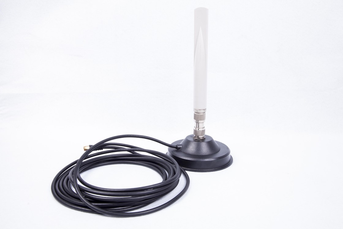
7 dBi 2.4G 5.8G Dual Band WIFI Bluetooth Antenna With Magnetic Mount
Detail Product Description
Frequency: 2400~2500 MHz; 5150~5850 MHz
S.W.R: 1.5 MAX
Impedance: 50 ohm
Peak Gain: 7 dBi
Cable: RG 174 Cable
Connector: N Connector Male
Application:
Specification
|
A. Electrical Characteristics |
||
|
Frequency |
2400~2500 MHz; 5150~5850 MHz |
|
|
Impedance |
50 ohm |
|
|
S.W.R |
1.5 MAX |
|
|
Peak Gain |
7 dB |
|
|
Return Loss |
>= 10 dB |
|
|
B. Material & Mechanical Characteristics |
||
|
Cable Type |
RG 174 Cable |
|
|
Connector Type |
N Connector Male |
|
|
Pull Test |
>= 3.0Kg |
|
|
C. Environmental |
|
|
|
Operation Temperature |
- 40 ˚C ~ + 65 ˚C |
|
|
Storage Temperature |
- 40 ˚C ~ +80˚C |
|
Characteristics and Reliability Test
|
Test Items |
Test Condition and Procedure |
Requirements |
|
|
C1 |
S.W.R. |
Set DUT on Network Analyzer; make individual calibration to test |
Directive DUT specification |
|
M1 |
Vibration |
MIL-STD-202G, 201A Amplitude: 0.03 inch (0.76mm); Freq: 10 to 55 Hz 3 directions; 2 hours for each direction |
1. No Visual Damage 2. Frequency Tol.<= 5% |
|
M2 |
Random Drop |
Height: 1.5 Meter; 3 directions; 1 time for each direction |
1. No parts separated 2. Frequency Tol.<= 5% |
|
M3 |
Solderability |
MIL-STD-202G, 210F, cond. A Solder iron: 350±10°C; Duration: 5 seconds |
1. Mounted on PCB 2. No Visual Damage |
|
M4 |
Terminal- Pull Test |
MIL-STD-202G, 211A, cond. A Holding with individual specification; force applied to axis of terminal |
1. Directive DUT specification 2. Frequency Tol.<= 5% |
|
M5 |
Dimension |
Inspection of dimension, color, material, package, surface process |
Directive DUT specification |
|
E1 |
Salt Spray |
MIL-STD-202G, 101E, cond. B Temp: 35°C; RH: >= 95%; NaCl solution: >= 5%; Time: 48 hours |
After 2 Hours Recovery 1. No Visual Damage 2. Frequency Tol.<= 5% |
|
E2 |
Humidity |
MIL-STD-202G, 103B, cond. B Temp: 40°C; RH: >= 95%; Time: 48 hours |
After 2 Hours Recovery 1. No Visual Damage 2. Frequency Tol.<= 5% |
|
E3 |
Thermal Shock |
1 Cycle: - 40°C (30 minutes) to + 80°C (30 minutes) Cycles: 24 |
After 2 Hours Recovery 1. No Visual Damage 2. Frequency Tol.<= 5% |
|
E4 |
Life (High Temp.) |
MIL-STD-202G, 108A, cond. A Temp: 85°C; Time: 96 hours |
After 2 Hours Recovery 1. No Visual Damage 2. Frequency Tol.<= 5% |
|
R1 |
RoHS |
With Reference to IEC 62321:2008 with flow chart |
Directive RoHS 2002/95/EC |
|
R2 |
PFOS |
With Reference to USA EPA 3540C:1996 by LC/MS |
Directive RoHS 2006/122/EC |
|
R3 |
PFOA |
With Reference to USA EPA 3540C:1996 by LC/MS |
Directive RoHS 2006/122/EC |
S Parameter Test Data
![]()